Joystick to Differential Drive (Arduino)
When you are building robots, one of the most common chassis you find are the ones that use Differential Drive. This means they have a motor per wheel, might be threaded, two wheels and a caster, 4 wheels, etc.
Posted by Simar Mann Singh on 02 May, 2022
When you are building robots, one of the most common chassis you find are the ones that use Differential Drive. This means they have a motor per wheel, might be threaded, two wheels and a caster, 4 wheels, etc.
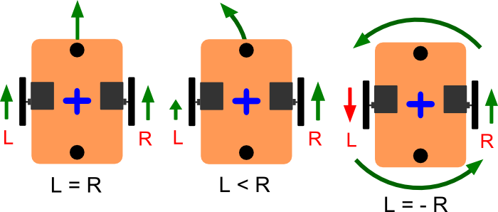
One way of driving this differential drive robots is sending PWM signals to each motor. But how do you convert for example the signals from a Joystick, (or any Cartesian pair of coordinates, like a direction vector) to the specific order for each wheel?
That is where this function is required. It receives a pair of cartesian x, and y coordinates, and calculates the differential drive output (right and left wheel commands) you will need to send to the motors.
This function will generate an output as can be seen in the following image:
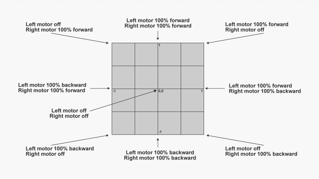
LeftMotorOutput and RightMotorOutput will hold the values you should send to the right and left motors.
You can also configure the limits of x, y, and right and left motors by using the 4 constants defined on top of the code, this is handy to adapt the function to your specific scenario.
#define DDRIVE_MIN -100 //The minimum value x or y can be.
#define DDRIVE_MAX 100  //The maximum value x or y can be.
#define MOTOR_MIN_PWM -255 //The minimum value the motor output can be.
#define MOTOR_MAX_PWM 255 //The maximum value the motor output can be.

int LeftMotorOutput; //will hold the calculated output for the left motor
int RightMotorOutput; //will hold the calculated output for the right motor


void DifferentialDriveService::CalculateTankDrive(float x, float y)
{
 float rawLeft;
 float rawRight;
 float RawLeft;
 float RawRight;


 // first Compute the angle in deg
 // First hypotenuse
 float z = sqrt(x * x + y * y);

// angle in radians
 float rad = acos(abs(x) / z);

// Cataer for NaN values
 if (isnan(rad) == true) {
 rad = 0;
 }

// and in degrees
 float angle = rad * 180 / PI;

// Now angle indicates the measure of turn
 // Along a straight line, with an angle o, the turn co-efficient is same
 // this applies for angles between 0-90, with angle 0 the co-eff is -1
 // with angle 45, the co-efficient is 0 and with angle 90, it is 1

float tcoeff = -1 + (angle / 90) * 2;
 float turn = tcoeff * abs(abs(y) - abs(x));
 turn = round(turn * 100) / 100;

// And max of y or x is the movement
 float mov = max(abs(y), abs(x));

// First and third quadrant
 if ((x >= 0 && y >= 0) || (x < 0 && y < 0))
 {
 rawLeft = mov; rawRight = turn;
 }
 else
 {
 rawRight = mov; rawLeft = turn;
 }

// Reverse polarity
 if (y < 0) {
 rawLeft = 0 - rawLeft;
 rawRight = 0 - rawRight;
 }

// Update the values
 RawLeft = rawLeft;
 RawRight = rawRight;

// Map the values onto the defined rang
 LeftMotorOutput = map(rawLeft, DDRIVE_MIN, DDRIVE_MAX, MOTOR_MIN_PWM, MOTOR_MAX_PWM);
 RightMotorOutput = map(rawRight, DDRIVE_MIN, DDRIVE_MAX, MOTOR_MIN_PWM, MOTOR_MAX_PWM);
}
If you find this code snippet useful, need help to make it work, or to understand it, please leave a comment and we can talk about it!