Aum2: Raspberry Pi Zero W based robot
As soon as I got my Raspberry Pi Zero W, I started thinking how to test it. I chose to use it as brain of one of those standard robot bases available online.
Posted by Simar Mann Singh on 06 Oct, 2017
As soon as I got my Raspberry Pi Zero W, I started thinking how to test it. I chose to use it as brain of one of those standard robot bases available online.
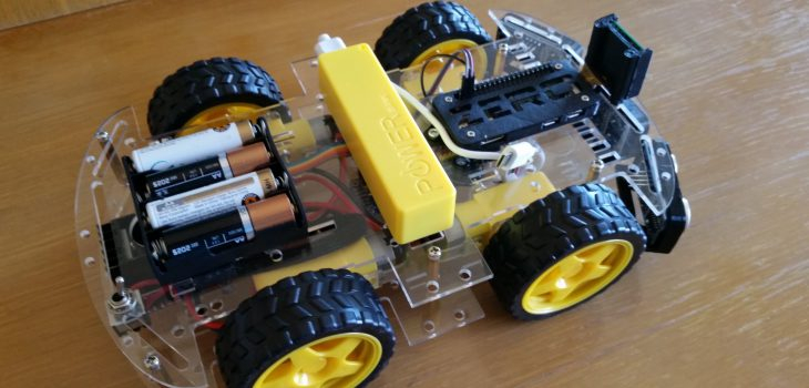
I bought an Arduino Smart Car kit in Aliexpress, there is a lot of information online about this chassis, and it’s not expensive at all.
As I mentioned, the brain of the robot is a Raspberry Pi Zero W, as can be seen in the images, I also connected to it the camera module and 3 SR04 ultrasonic distance sensors.

I’m not using them right now, but I thought it was a good idea to lay out all the hardware in place, so I can avoid surprises down the path, when I finally want to use them.

Another choice I made was to use two different batteries, one for electronics, and another for the motors. This ensures I wont get weird stuff when the motors are draining current.
To control the motors I used a 16 servo driver, and I think that was the best decision I made on this robot. It simplified a lot the coding and made it look a lot more tidy, since many cables staid on the lower level instead of needing to connect them to the RPi.
Programming in python was so simple, that I am regretting not making the change long before. I love object oriented programming, and python gave me the perfect combination between OOP an access to hardware.
The first task I wanted to tackle on this robot was enabling it to be remote controled.
To accomplish this I am using my android’s phone accelerometer, with an app that sends to an IP address and port, using UDP protocol, the changes in the accelerometer (and other stuff, that I´m not currently using. You can download the app here.
On this video you can see how it worked out:
TODO Add video
So I’m pretty happy with it, it’s responsive enough and super intuitive to drive. I would make it more powerful though.. I might in another iteration.
So, lets go to the code..
I divided the code in these files, that I will be explaining one by one:
- aum2.py
- l298NDrive.py
- remoteControl.py
- utils.py
aum2.py
This is the main entry point of the application, and contains the robot class:
import RPi.GPIO as GPIO
from twisted.internet import reactor, task
import l298NDrive
import remoteControl
import logging
import utils

logging.basicConfig(level=logging.WARN)
log = logging.getLogger('Aum2')

enableMotors = True # Motors can be disabled for testing with this
runFrequency = 1 # The frequency on wich the main Task will be ran

class Aum2(object):

    def __init__(self):
        log.debug("Initializing Aum2 robot...")
        # Configuration
        self.port = 5555 # Port to open so the remote can connect
        GPIO.setmode(GPIO.BOARD)
        # Configure min and max servo pulse lengths
        # Keep in mind these are not pins but servo outs
        self.motors = l298NDrive.L298NDrive(10, 11, 12, 13, 14, 15, enableMotors)
        self.rc = remoteControl.RemoteControl(self.port)

    def processRemoteCommand(self, cmd):
        (vr, vl) = utils.joystickToDiff(cmd.x, cmd.y, -9.8, 9.8, -4095, 4095)
        self.motors.setSpeeds(int(vr), int(-vl))

    def run(self):
        print("running...")

    def start(self):
        self.rc.start(self.processRemoteCommand)
        l = task.LoopingCall(self.run)
        l.start(runFrequency) # run will be called with this frequency

# Gather our code in a main() function
def main():
    robot = Aum2()
    robot.start()
    reactor.run()

# Standard boilerplate to call the main() function to begin
# the program.
if __name__ == '__main__':
    main()
Some points I’d like to comment about this file:
- I am using the twisted library to be able to coordinate the Remote Control orders coming from an UDP server (I’ll show that in its corresponding source file) and the main Run method of the robot. As you can see, that method is doing nothing right now, but the idea is to add there the code to make the robot a little more autonomous.
- The processRemoteCommand method will be called each time we get a message from the remote control, so we should act accordingly.
- The start method is were I configure the two things that needs to be coordinated: listening for remote commands, and the robots run method.
remoteControl.py
This file contains two classes, the RemoteControl class, and the RCCommand class
import logging
import traceback
from twisted.internet.protocol import DatagramProtocol
from twisted.internet import reactor
import utils

log = logging.getLogger('RemoteControl')


class RemoteControl(DatagramProtocol):

    def __init__(self, port):
        self.port = port

    def start(self, onCommandReceived):
        log.debug("Initializing RemoteControl...")
        self.onCommandReceived = onCommandReceived
        reactor.listenUDP(self.port, self)

    def datagramReceived(self, data, addr):
        try:
            log.debug("Received %r from %s" % (data, addr))
            command = RCCommand(data)
            self.onCommandReceived(command)
        except (KeyboardInterrupt, SystemExit):
            raise
        except:
            traceback.print_exc()


class RCCommand(object):
    # Timestamp [sec], sensorid, x, y, z, sensorid, x, y, z, sensorid, x, y, z
    # 890.71558, 3, 0.076, 9.809, 0.565, ...

    def __init__(self, message):
        self.x = 0
        self.y = 0
        self.z = 0
        self.values = message.split(",")

        if len(self.values) >= 5 and self.values[1].strip() == "3":
            self.x = -float(self.values[3].strip())
            self.y = -float(self.values[2].strip())
            self.z = float(self.values[4].strip())
            log.debug("x={} y={} z={}".format(self.x, self.y, self.z))
        else:
            log.warn("Invalid message: {}".format(message))
Again, the RemoteControl class, uses twisted framework to listen for UDP packages sent by the Android phone running the Wireless IMU app. This application sends messages with this structure:
890.71558, 3, 0.076, 9.809, 0.565, 4, -0.559, 0.032, -0.134, 5, -21.660,-36.960,-28.140
I’m only interested in the part of the message I highlighted above, this would be, sensor id 3, and the three measurements provided by the accelerometer (0.076, 9.809, 0.565). As you can see in the code, the class RCCommand translates the useful par of this message into the x, and y values we need for the robot, where x is the axis that goes from front to back, and y, goes from side to side. I also have code for the z axis, but I’m not using that for now.
l298NDrive.py
This is the file responsible to control the motors. For this it sends orders to the the 16 Servo driver, which is connected to the L298N Motor driver. I think I will probably reusing this class on every Raspberry Pi robot I build. It’s really simple and makes what it needs without complicating anything.
import Adafruit_PCA9685
import logging
import math
import utils

log = logging.getLogger('L298NDrive')


class L298NDrive(object):

    def __init__(self, enA, in1, in2, in3, in4, enB, enabled):
        log.debug("Initializing L298Drive...")
        self.minPwm = 0
        self.MaxPwm = 4095
        self.enA = enA
        self.in1 = in1
        self.in2 = in2
        self.in3 = in3
        self.in4 = in4
        self.enB = enB
        self.enabled = enabled
        if enabled:
            self.enable()

    def enable(self):
        self.enabled = True
        # Initialise the PCA9685 using the default address (0x40).
        self.pwm = Adafruit_PCA9685.PCA9685()
        self.setSpeeds(0, 0)

    def disable(self):
        self.enabled = False
        self.setSpeeds(0, 0)
        # Initialise the PCA9685 using the default address (0x40).
        self.pwm = None

    def setSpeeds(self, rSpeed, lSpeed):
        self.setSpeed(1, rSpeed)
        self.setSpeed(2, lSpeed)

    def setSpeed(self, motor, speed):
        pwm = int(math.fabs(speed))
        log.info("Motor: {} speed: {} pwm: {}".format(motor, speed, pwm))

        if motor == 1:
            if speed >= 0:
                if self.enabled:
                    self.pwm.set_pwm(self.in1, 0, 0)
                    self.pwm.set_pwm(self.in2, 0, self.MaxPwm)
            else:
                if self.enabled:
                    self.pwm.set_pwm(self.in1, 0, self.MaxPwm)
                    self.pwm.set_pwm(self.in2, 0, 0)
            if self.enabled:
                self.pwm.set_pwm(self.enA, 0, pwm)
       else: # motor == 2
            if speed >= 0:
                if self.enabled:
                    self.pwm.set_pwm(self.in3, 0, 0)
                    self.pwm.set_pwm(self.in4, 0, self.MaxPwm)
            else:
                if self.enabled:
                    self.pwm.set_pwm(self.in3, 0, self.MaxPwm)
                    self.pwm.set_pwm(self.in4, 0, 0)
            if self.enabled:
                self.pwm.set_pwm(self.enB, 0, pwm)
As can be seen, the main part of the code is in the method setSpeed(self, motor, speed) this method receives the motor number to configure (1=right, 2= left) and tells the Servo Driver what to do with the pins associated with that motor.
Maybe a little of explanation should be given to understand why I’m doing what I’m doing there..
The L298N motor driver
Uses 6 pins to drive two motors:
- enA Is used to tell the speed (using PWM) we want the motor to turn
- in1 When powered, Tells the driver that the motor 1 should move in one direction (in2 should be OFF)
- in2 When powered, Tells the driver that the motor 1 should move in the opposite direction (in1 should be OFF)
- in3 When powered, Tells the driver that the motor 2 should move in one direction (in4 should be OFF)
- in4 When powered, Tells the driver that the motor 2 should move in the opposite direction (in4 should be OFF)
- enB Is used to tell the speed (using PWM) we want the motor to turn
So in our case, as I’m using a servo driver for all of the pins (and only 2 of them need PWM):
when I do this:
self.pwm.set_pwm(self.in1, 0, 0)
I’m really telling the servo driver that that pin (in1) should be OFF during all the PWM cicle, (so I turn OFF that pin)
and when I do this:
self.pwm.set_pwm(self.in1, 0, self.MaxPwm)
’m really telling the servo driver that that pin (in1) should be in ON during all the PWM cicle, (so I turn ON that pin)
And then, when I do this:
self.pwm.set_pwm(self.enA, 0, pwm)
I use the real PWM pin, and set the pulse with that I was requested with the speed parameter.
utils.py
Finally the last peace of this. This doesn’t contain a class, but all the useful functions that I think I’ll be reusing in other places.
import math
import logging

log = logging.getLogger('utils')


def map(v, in_min, in_max, out_min, out_max):
    # Check that the value is at least in_min
    if v < in_min:
    v = in_min

    # Check that the value is at most in_max
    if v > in_max:
       v = in_max
    return (v - in_min) * (out_max - out_min) // (in_max - in_min) + out_min


def joystickToDiff(x, y, minJoystick, maxJoystick, minSpeed, maxSpeed):

    # If x and y are 0, then there is not much to calculate...
    if x == 0 and y == 0:
        return (0, 0)

    # First Compute the angle in deg
    # First hypotenuse
    z = math.sqrt(x * x + y * y)

    # angle in radians
    rad = math.acos(math.fabs(x) / z)

    # and in degrees
    angle = rad * 180 / math.pi

    # Now angle indicates the measure of turn
    # Along a straight line, with an angle o, the turn co-efficient is same
    # this applies for angles between 0-90, with angle 0 the coeff is -1
    # with angle 45, the co-efficient is 0 and with angle 90, it is 1

    tcoeff = -1 + (angle / 90) * 2
    turn = tcoeff * math.fabs(math.fabs(y) - math.fabs(x))
    turn = round(turn * 100, 0) / 100

    # And max of y or x is the movement
    mov = max(math.fabs(y), math.fabs(x))

    # First and third quadrant
    if (x >= 0 and y >= 0) or (x < 0 and y < 0):
        rawLeft = mov
        rawRight = turn
    else:
        rawRight = mov
        rawLeft = turn

    # Reverse polarity
    if y < 0:
        rawLeft = 0 - rawLeft
        rawRight = 0 - rawRight

    # minJoystick, maxJoystick, minSpeed, maxSpeed
    # Map the values onto the defined rang
    rightOut = map(rawRight, minJoystick, maxJoystick, minSpeed, maxSpeed)
    leftOut = map(rawLeft, minJoystick, maxJoystick, minSpeed, maxSpeed)

    log.debug("x={} y={}, rOut={}, lOut={}".format(x, y, rightOut, leftOut))
    return (rightOut, leftOut)
There are just two methods here, the first is a port from Arduino of the map function. It converts a value (v) within the specified input limits (inmin, inmax) to the corresponding value within the output range (outmin, outmax).
I added limits for the input value, so I only accept a v, that is within the inmin and inmax.
The other function I have (joystickToDiff) is a little more complex, but its purpose is to convert from an joystick pair of input values, to the required speeds of the right and left motors of a Differential drive robot. This output is delivered already converted to the range of speeds specified as parameters. You can find more details on this part on this previous article
I hope this article makes sense for you, and if I can help you in any way to make it work in your own robot, please let me know. If you see something I could improve in the article, or the code, please also let me know, I will hear your recommendations.